AC motors operate on the same basic principle, but by modifying their design slightly, you can tailor their performance to suit specific applications. In our previous post, we focused on AC induction motors for unidirectional use. In this article, we will explore how AC reversible motors and AC electromagnetic brake motors are ideal for start/stop, reversing, or vertical applications, and explain how they function.
Reversible Motors
Let's first clarify why these motors are called "reversible." All permanent split capacitor type AC motors are technically reversible. However, induction motors cannot reverse direction instantly—they must come to a complete stop first. Reversible motors, on the other hand, can change direction much more quickly. For example, while you can reverse an induction motor by swapping its lead wires, it typically has about a 30-revolution overrun, compared to just 5 revolutions in a reversible motor. This makes them more suitable for applications requiring instant reversal.
The term "overrun" refers to the number of motor shaft revolutions it takes for the motor to stop once power is removed. According to Newton’s First Law of Motion, an object in motion stays in motion unless acted upon by an external force—like friction. Induction motors have minimal internal friction, mainly from ball bearings, which results in longer overrun. Reversible motors, however, include a friction brake that significantly reduces this overrun.
| Reversible motors are ideal for applications like reversing conveyors, where quick stop-and-go or directional changes are needed. They generate more heat, so a 50% duty cycle is recommended (maximum 30 minutes of continuous operation). |
 |
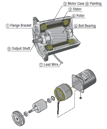
Design Comparison to Induction Motors
| Structure of Induction Motors |
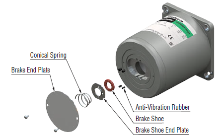
Structure of Reversible Motors |
 |
Same as induction motors, but with additional friction brake components:
|
The key difference between an induction motor and a reversible motor is the addition of a friction brake, which drastically reduces overrun and enables smooth start/stop and reversing operations. A spring continuously presses the friction brake against the armature, reducing overrun when the motor stops. The holding torque from the friction brake is only about 10% of the motor's output torque, but it can be increased through gear ratios. It's designed to reduce overrun, not to hold a load vertically.
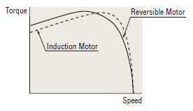
Another design feature is the use of a balanced winding, meaning both primary and secondary windings have equal resistance and inductance. This allows for consistent torque regardless of the direction of rotation. Combined with the friction brake, this enables on-the-fly direction changes.
| Since the friction brake constantly rubs against the armature, a higher-rated capacitor is used to increase starting torque during start-up and reversal. Due to higher operating temperatures, the duty cycle is limited to 50% (50% on, 50% off). However, as long as the motor case temperature remains below 100°C, the motor will perform reliably. |
 |
Theory of Operation
When power is applied to the copper windings in the stator, a rotating magnetic field is created around the rotor at the speed of the AC oscillations. Using Fleming’s left-hand rule, this moving magnetic field induces current in the aluminum bars of the steel rotor, generating opposing magnetic fields (Lenz’s Law). These rotor fields then interact with the stator’s rotating field, causing the rotor to rotate.
|
Want to know more about operational theory of AC motors?
 hbspt.cta._relativeUrls=true;hbspt.cta.load(2284573, '790f02f2-dde7-4197-bc9e-3256c1f04309', {"useNewLoader":"true","region":"na1"}); hbspt.cta._relativeUrls=true;hbspt.cta.load(2284573, '790f02f2-dde7-4197-bc9e-3256c1f04309', {"useNewLoader":"true","region":"na1"});
|
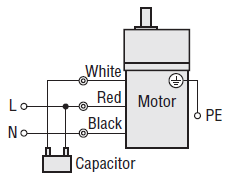
Wiring
Here is the wiring diagram for single-phase reversible motors, similar to single-phase induction motors. Three-phase motors are usually used with inverters or VFDs for continuous speed control, so three-phase reversible motors are less common. Note that the rotation direction is indicated when viewed from the output shaft side of the motor.

While the operational theory is the same for all single-phase permanent split capacitor type AC motors, lead wire colors may vary. For a standard 3-wire motor, the lead wire colors are white, red, and black. Black is always connected to neutral (N), and both white and black are connected to the two terminals of the dedicated capacitor. When the live (L) is connected to either the black or red via the capacitor terminal, the motor rotates in the intended direction. For terminal box type motors, the theory is the same, but the terminals are labeled Z2, U2, and U1.
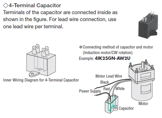
The Capacitor
For single-phase motors, the capacitor is crucial for starting. Without the starting torque provided by the capacitor, you would need to manually rotate the motor shaft to start it. Think of it like the old propellers on vintage airplanes. Always ensure the capacitor is properly wired, as this was a common issue I encountered as a tech support engineer.
Here’s an example of a 4-terminal capacitor wired to a single-phase motor.
| Don't be confused by the number of terminals on the capacitor. The inner wiring diagram shows that the two closest terminals are internally connected. Electrically, this is equivalent to traditional two-terminal capacitors. |
 |
| As with all motors, make sure to ground the motor using its dedicated protective earth grounding terminal (PE) to prevent electrical shocks or injuries. |
 |
Here’s a video demonstrating the standard wiring setup.
 hbspt.cta._relativeUrls=true;hbspt.cta.load(2284573, '1fbc2381-431c-4536-906f-16d817df9f61', {"useNewLoader":"true","region":"na1"});
Electromagnetic Brake Motors
Similar to reversible motors, electromagnetic brake motors are reversible motors equipped with a power-off-activated electromagnetic brake. Since the base motor is reversible, the duty cycle remains at 50%. The main difference is that electromagnetic brake motors offer shorter overrun and greater holding torque.
| Electromagnetic brake motors are ideal for vertical applications, such as elevator systems. The power-off-activated electromagnetic brake produces nearly the motor’s rated torque, ensuring safety for both the load and personnel in case of a power failure during operation. |
 |
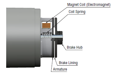
The electromagnetic brake is designed to lock the motor shaft and hold the load in place. It also reduces the overrun from 30 revolutions to about 2 revolutions. For start/stop applications, the maximum operating cycle of the electromagnetic brake is 50 cycles per minute or less. For higher cycles, consider using a brake pack, clutch-brake motor, or high-efficiency stepper motor.
| The electromagnetic brake uses the same voltage as the motor and engages to lock the load. When the magnet coil is energized, it becomes an electromagnet and attracts the armature against the spring force, releasing the brake. When the coil is de-energized, the spring presses the armature onto the brake hub, locking the motor shaft in place. |
 |
Compared to induction and reversible motors, the wiring for electromagnetic brake motors is slightly more complex due to the additional components involved. A capacitor is also required for single-phase models. Three-phase electromagnetic brake motors are available for variable speed applications, as they are based on continuous-duty induction motors rather than duty-limited reversible motors.
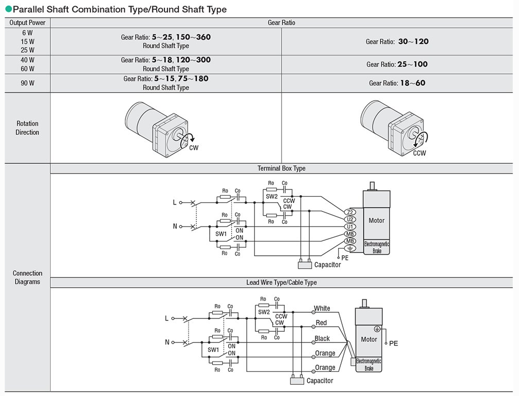
If you follow the wiring diagram above and use the specified switches, the electromagnetic brake will automatically engage when the motor stops and disengage when the motor runs. The SW1 switch controls both the motor and brake power, while the SW2 switch controls the motor direction.
Here’s a demonstration video showing the proper wiring, including circuit breakers, switches, and CR modules for surge suppression.
Overrun and Duty Cycle Comparison
Here’s a summary of the main differences between induction motors, reversible motors, and electromagnetic brake motors.
| Type of Motor |
Overrun |
Duty Cycle |
| Induction Motor |
30~40 revolutions |
Continuous |
| Reversible Motors |
5~6 revolutions |
50% |
| Electromagnetic Brake Motors |
2~3 revolutions |
50% |
The overrun value refers to the motor shaft. Adding a gearhead with a high ratio, increasing friction, or reducing load inertia can help decrease the overrun.
The duty cycles mentioned are recommended values. As a general rule, keeping the motor case temperature below 100°C ensures safe operation.
That’s it for AC reversible motors and AC electromagnetic brake motors. Stay tuned for a post on torque-speed characteristics of AC motors, and remember to subscribe!
|
Learn more about KII & KIIS Series
Here's a short video explaining the KII & KIIS Series AC induction motors, AC reversible motors, and AC electromagnetic brake motors, along with their typical applications.
|
|
hbspt.cta._relativeUrls=true;hbspt.cta.load(2284573, '1fbc2381-431c-4536-906f-16d817df9f61', {"useNewLoader":"true","region":"na1"});
Industry Deodorant Masterbatch
Odors Removal Agent,Deodorant Masterbatch,Masterbatch Absorbing Agent,Industry Deodorant Masterbatch
Ningbo Jiahe New Materials Technology Co.,ltd , https://www.cnjhchem.com