Insulated Shipping Box,Thermal Corrugated Foil Box,Foil Shield Food Handle Box,Portable Insulated Food Picnic Cooler Box Huizhou Green Foil Insulation Co., Ltd , https://www.heatinsulator.com
Key words Dingyang Oscilloscope SIGLENT Power Supply Noise Power Supply Ripple Test Measurement SDS1000 Series 1. Measurement Method Measuring Ripple First of all, we must know the correct measurement method. Many engineers take a digital oscilloscope to measure the ripple value of several hundred mV, which is comparable to the specification of the parameters. This is definitely caused by incorrect measurement methods. The following takes the SDS1000 of Dingyang Company as an example to perform the correct operation steps for routine measurement.
Open the bandwidth limit function of SDS1000, limit the oscilloscope bandwidth to 20MHz, or open the digital filter to select the low-pass filter function, adjust the limit bandwidth value of the low-pass filter, hit below 20MHz, and the specific effect can be fed back from the waveform. The purpose is to avoid the high-frequency noise of the digital circuit from affecting the ripple measurement and to ensure the accuracy of the measurement.
Set the coupling mode to AC coupling to prevent the oscilloscope from displaying the ripple signal because the DC signal is too large. It is convenient to measure (to observe the ripple in a smaller position and not to care about the DC level);
Ensure that the probe is grounded as short as possible (the main reason for measuring ripple fluctuations of more than 100 mV is that the grounding wire is too long). The probe's ground wire and housing can be removed to expose the probe crust and the ground wire is wound around the probe crust. This can be effective. Ensure that the length of the grounding wire is less than 1cm; (This is the key point. The ripple is a small signal, and the inductance effect caused by the long grounding wire will cause large noise interference in the measurement.)
The oscilloscope is grounded and grounded only by the ground of the probe and the reference point of the test signal. Do not share ground with the test equipment by other means (this will probably introduce a large amount of ground noise to the ripple measurement). For example, when the oscilloscope and other instruments are plugged together, the switches of other instruments may cause noise interference to the test through the ground wire.
The following figure shows the influence of the length of the ground wire on a square wave signal: 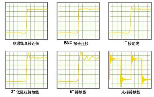
2, the requirements of the instrument oscilloscope parameters:
Support bandwidth limit or digital filter function: General oscilloscope supports 20MHz bandwidth limit, there are more advanced digital filtering functions, such as: SDS1000 series.
Probe requirements:
In order to make the grounding wire as short as possible, a short test needle can be configured for the probe, or a short grounding wire can be made by itself: remove the probe grounding wire cover, and use the wire to wind the grounding short wire by itself. The copper wire in the wire of the fifth type is recommended, and the strength is moderate. Solder wire, aluminum wire, etc. can also be used.
Select 1X no attenuation gear, the general passive probe in the 1X gear, the bandwidth is limited to 6MHz/10MHz bandwidth, so that the front-end can effectively filter out high-frequency noise interference and reduce the impact of ripple measurement. If 10X gear is selected, it will not only have no filtering effect, but also will cause serious attenuation of the ripple signal, which will increase the difficulty of observation.
3, actually test a ripple pattern:
To measure a power ripple, first test the ripple with a long ground wire: 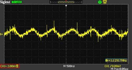
Connect the metal shell of the probe directly to the ground as above to test the ripple: 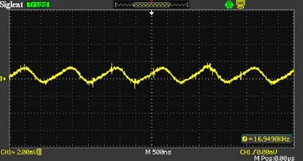
Dingyang oscilloscope is used to test the power supply ripple
Abstract: Today's electronic devices are endless, and various power supply modules/power supplies are changing with each passing day. How to accurately and conveniently test power supply ripple and screen power supplies that meet their requirements has become a problem that most engineers must face. How to use a digital oscilloscope to test power supply ripple has become a problem that must be faced by a new generation of companies.
Figure 1.1 Inductance Effect of Probe Ground Wire
Figure 3.1 Power supply 0.18V output, ripple as above (2mv/div SIGLENT automatically open bandwidth limit, convenient ripple measurement)
Figure 3.2 Minimize the length of the ground wire, obviously the signal quality is much better